View Frustum Culling Using Axis-Aligned Bounding Boxes (AABBs)
Recently I was able to implement view frustum culling on both the CPU and GPU for the StratusGFX rendering engine. In this article I will walk through the process of generating and incrementally updating Axis-Aligned Bounding Boxes (AABBs) from a mesh and then extracting the view frustum planes in world space to check the AABBs against them.
What is an AABB?
An AABB is a rectangle that is always aligned to the world basis vectors (will never be rotated) and wraps around a mesh such that every polygon of the mesh is enclosed by the AABB. It will look something like this:
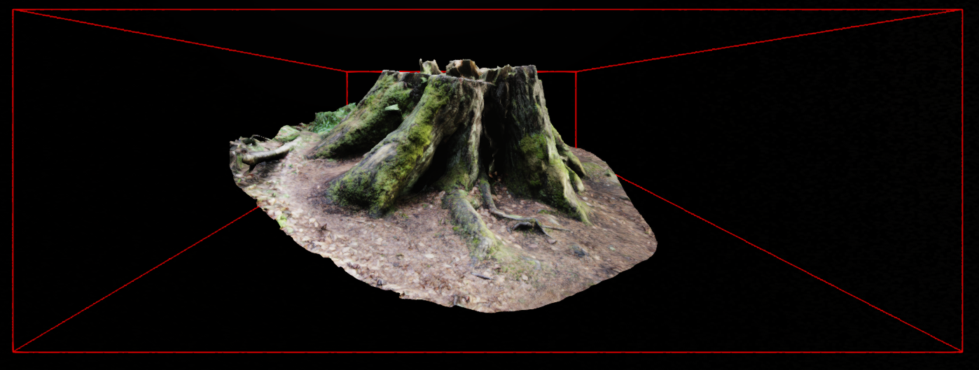
Here the red lines show the bounding box for the tree stump. Notice that even though the tree stump is rotated slightly, its AABB is completely aligned to the basis vectors without any rotation at all.
Motivation
Let’s say we have a scene that has grown in complexity to include many instanced meshes totaling tens of millions of triangles in total. These meshes are spread out so that they won’t all by visible on the screen at once.
Without some way to quickly cull objects that are currently not visible, we would be forced to send everything to the GPU and allow it to discard whatever is outside the view frustum. This results in a lot of extra work for the GPU and for complex scenes could completely destroy performance.
The benefit of wrapping all complex geometry inside of simple bounding boxes is that it enables us to perform a few very simple tests per group of geometry to answer the question “Is this object potentially visible?” Since the bounding box completely encloses the underlying mesh, if it is all or partly within the view frustum, there’s a good chance at least part of the mesh is visible. But if the bounding box is completely outside of the view frustum then we know for sure it is not visible and we don’t bother sending it to the GPU to be drawn.
Creating AABBs
We will be generating the bounding boxes in local (object) space for each mesh that we load from file. When generating the bounding boxes we don’t even need to pretransform the mesh relative to its parent (though it would still work if you did).
There are multiple different ways to store the bounding box information. This article stores them as min/max vertices. The algorithm is as follows:
struct AABB {
    // If doing GPU frustum culling be careful of alignment. For example,
    // using GLSL it would be best to store these both as vec4 or an
    // array of 3 floats each.
    glm::vec3 vmin;
    glm::vec3 vmax;
};

AABB CreateBoundingBox(const std::vector<glm::vec3>& vertices) {

    // vmin/vmax are both initialized to the first vertex
    glm::vec3 vmin = vertices[0];
    glm::vec3 vmax = vmin;

    // Start looping from vertex 1 onwards
    for (size_t i = 1; i < vertices.size(); ++i) {
        const glm::vec3& current = vertices[i];
        vmin = glm::min(vmin, current);
        vmax = glm::max(vmax, current);
    }

    AABB result;
    result.vmin = vmin;
    result.vmax = vmax;

    return result;
}
Once this function returns we have a valid bounding box represented by the minimum and maximum vertices in local (object) space.
Accounting For Transformation
Now that we have the bounding box created in local space per mesh, what happens after we transform the mesh relative to its parent, reposition it within the world, or animate the mesh in some way? Our bounding box becomes incorrect! Since we are maintaining the property of axis alignment, we cannot just rotate the AABB.
A brute force approach would be to loop through the transformed mesh vertices and recompute the bounding box each time the mesh is changed. This would work but would be way too slow.
What we are going to do instead is to recompute the bounding box using the transformed corners of the old bounding box. This means that all we need to do is convert vmin/vmax into 8 transformed corners representing the box, then use these 8 transformed corners to compute a new vmin/vmax and this will be our new bounding box for the mesh. This is the result:
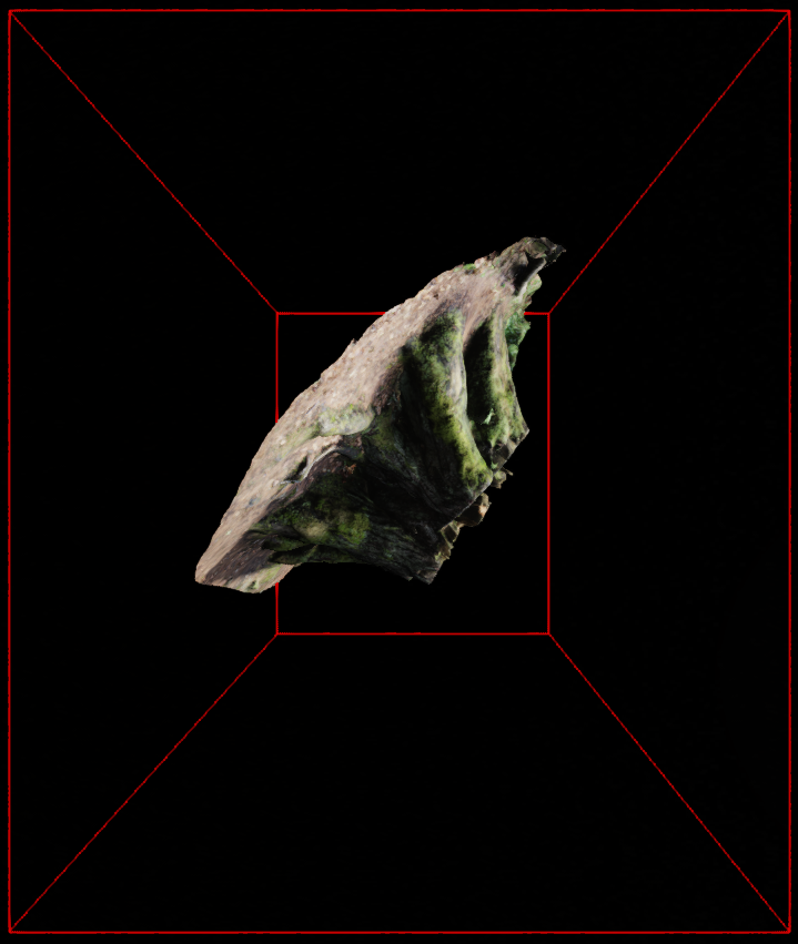
Notice how after the mesh is rotated, the bounding box changes accordingly but two important properties are maintained:
1) The new bounding box still fully encloses the mesh
2) The new bounding box is axis aligned (no rotation whatsoever)
It should be noted that one important downside to this approach (and to axis aligned bounding boxes in general) is that the generated bounding box isn’t ideal in the sense that it does fully enclose the mesh, but it is far larger than it needs to be. If the goal is to have the most perfect fit possible while still using boxes, Oriented Bounding Boxes (OBB) should be used instead or adopt a bounding volume hierarchy (BVH) approach.
In practice AABBs not being an ideal fit for the underlying mesh means we will have false positives (it will say the mesh may be visible when it’s not leading to some amount of wasted GPU work). Luckily we will never have false negatives: if it says the mesh is not visible, it means it is definitely not visible.
Here is the algorithm for recomputing a mesh’s bounding box using the old bounding box:
AABB RecomputeBoundingBox(const AABB& old, const glm::mat4& transform) {
    // First extract the 8 transformed corners of the box using vmin/vmax
    const glm::vec3& vmin = old.vmin;
    const glm::vec3& vmax = old.vmax;

    const glm::vec3 corners[8] = {
        glm::vec3(transform * glm::vec4(vmin.x, vmin.y, vmin.z, 1.0f)),
        glm::vec3(transform * glm::vec4(vmin.x, vmax.y, vmin.z, 1.0f)),
        glm::vec3(transform * glm::vec4(vmin.x, vmin.y, vmax.z, 1.0f)),
        glm::vec3(transform * glm::vec4(vmin.x, vmax.y, vmax.z, 1.0f)),
        glm::vec3(transform * glm::vec4(vmax.x, vmin.y, vmin.z, 1.0f)),
        glm::vec3(transform * glm::vec4(vmax.x, vmax.y, vmin.z, 1.0f)),
        glm::vec3(transform * glm::vec4(vmax.x, vmin.y, vmax.z, 1.0f)),
        glm::vec3(transform * glm::vec4(vmax.x, vmax.y, vmax.z, 1.0f))
    };

    // Now apply the min/max algorithm from before using the 8 transformed
    // corners
    glm::vec3 newVmin = corners[0];
    glm::vec3 newVmax = newVmin;

    // Start looping from corner 1 onwards
    for (size_t i = 1; i < 8; ++i) {
        const glm::vec3& current = corners[i];
        newVmin = glm::min(newVmin, current);
        newVmax = glm::max(newVmax, current);
    }

    // Now pack them into our new bounding box
    AABB result;
    result.vmin = newVmin;
    result.vmax = newVmax;

    return result;
}
Extracting View Frustum Planes In World Space
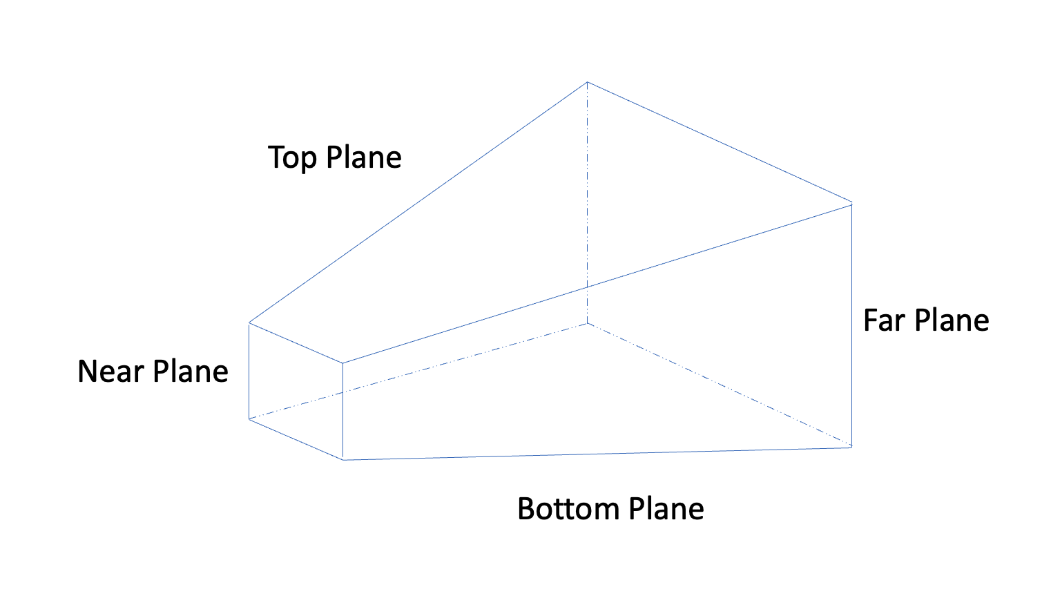
When using a perspective projection, the resulting view frustum looks like a pyramid with the top cut off. It is defined by 6 planes: near and far, top and bottom, left and right. For each plane its normal is pointing inward towards the center of the frustum.
What we are going to do is extract these 6 planes from the combined view-projection matrix which will give us all 6 planes in world space. This is important because our final, transformed AABB per mesh is also defined in world space, so we want to do all view frustum culling in world space as well.
// projection        - view space to clip space
// view              - world space to view space
// projection * view - world space to clip space
const glm::mat4 vp  = projection * view;

// By default, glm uses a right handed coordinate space so we
// will first transpose the matrix so that we can easily extract the
// planes
const glm::mat4 vpt = glm::transpose(vp);

const std::vector<glm::vec4> frustumPlanes = {
    // left, right, bottom, top
    (vpt[3] + vpt[0]),
    (vpt[3] - vpt[0]),
    (vpt[3] + vpt[1]),
    (vpt[3] - vpt[1]),
    // near, far
    (vpt[3] + vpt[2]),
    (vpt[3] - vpt[2]),
};
Now we have all 6 view frustum planes defined in world space.
Note: if for your renderer you are using a far plane defined as being infinitely far away, you could opt to only check it against 5 of the planes and skip the far plane.
Performing View Frustum Culling
Above I mentioned that the view frustum planes all have a normal pointing inward towards the center of the frustum. This is important to keep in mind because we can use the following properties of the dot product:
- Taking the dot product of a plane and a point is positive if the point is in front the plane along the direction of the plane’s normal, and
- Taking the dot product of a plane and a point is 0 if the point is on the plane, and
- Taking the dot product of a plane and a point is negative if the point is behind the plane
So what we are going to do for each bounding box is convert it to 8 world space points, then check each point against each plane using the dot product. If the dot product returns negative for every point, we know that the bounding box is completely outside of the view frustum and therefore not visible. If even one of the dot products returns 0 or greater, we submit that mesh to the GPU to be drawn.
bool IsAabbVisible(const AABB& box,
                   const std::vector<glm::vec4>& frustumPlanes) {

    const glm::vec3& vmin = box.vmin;
    const glm::vec3& vmax = box.vmax;

    for (size_t i = 0; i < frustumPlanes.size(); ++i) {
        const glm::vec4& g = frustumPlanes[i];
        if ((glm::dot(g, glm::vec4(vmin.x, vmin.y, vmin.z, 1.0f)) < 0.0) &&
            (glm::dot(g, glm::vec4(vmax.x, vmin.y, vmin.z, 1.0f)) < 0.0) &&
            (glm::dot(g, glm::vec4(vmin.x, vmax.y, vmin.z, 1.0f)) < 0.0) &&
            (glm::dot(g, glm::vec4(vmax.x, vmax.y, vmin.z, 1.0f)) < 0.0) &&
            (glm::dot(g, glm::vec4(vmin.x, vmin.y, vmax.z, 1.0f)) < 0.0) &&
            (glm::dot(g, glm::vec4(vmax.x, vmin.y, vmax.z, 1.0f)) < 0.0) &&
            (glm::dot(g, glm::vec4(vmin.x, vmax.y, vmax.z, 1.0f)) < 0.0) &&
            (glm::dot(g, glm::vec4(vmax.x, vmax.y, vmax.z, 1.0f)) < 0.0))
        {
            // Not visible - all returned negative
            return false;
        }
    }

    // Potentially visible
    return true;
}
Now all that’s left is to loop through each transformed mesh bounding box and call IsAabbVisible. For any that return false, skip it for that frame. For any that return true, send it to the GPU to be drawn.
Converting AABB Struct To Vertices For Debugging
If you end up wanting to render the AABBs for your scene for debugging purposes, you can create all 12 lines of the bounding box as follows:
std::vector<glm::vec3> GetAABBVertices(const AABB& box) {
    const glm::vec3& vmin = box.vmin;
    const glm::vec3& vmax = box.vmax;

    // First create the 8 corners
    const glm::vec3 corners[8] = {
        glm::vec3(vmin.x, vmin.y, vmin.z),
        glm::vec3(vmin.x, vmax.y, vmin.z),
        glm::vec3(vmin.x, vmin.y, vmax.z),
        glm::vec3(vmin.x, vmax.y, vmax.z),
        glm::vec3(vmax.x, vmin.y, vmin.z),
        glm::vec3(vmax.x, vmax.y, vmin.z),
        glm::vec3(vmax.x, vmin.y, vmax.z),
        glm::vec3(vmax.x, vmax.y, vmax.z)
    };

    // Now connect the corners to form 12 lines
    std::vector<glm::vec3> vertices = {
        corners[0], corners[1], // Line 1
        corners[2], corners[3], // Line 2
        corners[4], corners[5],
        corners[6], corners[7],

        corners[0], corners[2],
        corners[1], corners[3],
        corners[4], corners[6],
        corners[5], corners[7],

        corners[0], corners[4],
        corners[1], corners[5],
        corners[2], corners[6],
        corners[3], corners[7]  // Line 12
    };

    return vertices;
}
Now you have access to 12 lines that you can render with something like GL_LINES. Make sure that you pass the transformed bounding box into this function and not the original bounding box. This way any time the mesh is transformed you will be able to see the latest, updated bounding box for that mesh.
3D Model Used:
References
- https://math.stackexchange.com/questions/1330210/how-to-check-if-a-point-is-in-the-direction-of-the-normal-of-a-plane
- 3D Graphics Rendering Cookbook
- Foundations of Game Engine Development, Volumes 1 & 2